 |
 |
by DF2IR, Munich and Heidelberg
|
|
In German-speaking countries we call a radio transmission
“Funken” (= sparking). The radio operator is named “Funker”
(= Sparker). But where are the roots of theses designations? This document
will explain and clarify the roots about the German choice of words. Additional
it describes an experiment how the radio transmission was performed without
having tubes, transistors and oscillators.
1.0 The first Theory
Between 1861 and 1864 James Clerk Maxwell developed four equations,
the unified field theory of the electric and magnetic field. The equations
enabled him to calculate the distribution speed of the electro-magnetic wave.
He found, the distribution speed of the electro-magnetic wave is equal to
the speed of light. So he conclude, the electro-magnetic wave and the light
is the same. The only difference is the frequency (or wavelength). Also he
conclude, a free room distribution of the electro-magnetic wave is possible
[1, page 20, 54].
1.1 The Proof of the Free Room Distribution
In 1888 Heinrich Hertz was Professor of Physics at the Technical
University of Karlsruhe (Germany). He developed an experiment to demonstrate
the existence of the electro-magnetic field and the free room distribution
of an electro-magnetic wave. Hertz at his time has no tubes, no transistors
and no other electronic components to detect or generate electro-magnetic
waves. Heinrich Hertz used a high voltage spark. The spark occurs in a gap
at the middle of two dipole antenna parts. As a receiver Hertz uses a wire
ring having a little gap. With this experiment Hertz proofed the existence
and the free room traveling of electro-magnetic waves.
1.2 The Practical Use
Between 1894 and 1895, the Italian Guglielmo Marconi made first
experiments in radio transmissions [5, page 16]. The transmitter was based
on the high voltage spark. Marconi used a coherer to receive the transmission.
In June 1896 Marconi filed the first patent on a London Patent Office about
a radio transmitter and receiver [5, page 24]. Years later Marconi used very
powerful sparks to overcome the Atlantic Ocean. Now you know, why the
German-speaking counties using the word “Sparking” for the radio
transmission. High voltage sparks have been the first possibility to generate
traveling electromagnetic waves.
2. The Coherer
The coherer is a simple element and it is based on observations starting around 1830. People observed, that particles in the air arranged in line, if electric sparks are close. Out of such observations in 1890 the French Edouard Branly invented the coherer. Still nowadays the function of the coherer is not fully understood [3].
 |
Picture 1: Parts of the coherer
Picture 1 shows the components used for the (modern) coherer construction. The coherer consist of:
• a housing (e.g. glass tube or plastic tube)
• two electrodes (brass screws)
• metal powder which is placed between the two electrodes in the tube
• no vacuum is required
Nowadays we are able to build the coherer using plastic tubes as I have done. The construction of the two electrodes and the metal powder filled-in between the electrodes has a very high resistance, several 10e6 Ohm. If the coherer detects an electro-magnetic wave, the resistance goes down to a very low resistance (less then 10 Ohm). The disadvantage, the coherer does not self recover. If the coherer is in the conducting state, it needs a mechanic shock to recover back into the high resistance state.
In 1899 the Indian scientist Bose tested different materials to
use as coherer-material. His main task was to find a self recovering coherer.
However, he found silver or nickel powder as the best material for a sensitive
coherer. The second best material to make a coherer is aluminum powder [2].
Marconi uses for his coherer a mixture of silver and nickel powder. The
electrodes are made from silver too. The housing was glass [4]. Sometimes
the air in the glass was evacuated.
3. The Transmitter
A piezo from a gas lighter is good to generate a spark between the center of a dipole antenna. The dipole is mounted on an altered gas lighter. The length of the dipole is the only frequency determining element. The spark lights up in the little gap in the center of the dipole.
 |
Picture 2: The spark transmitter
3. 1 Possible Improvement
Decoupling the dipole connection from the wires coming from the
piezo by two inductivities may increase the transmission power. The inductivities
also may smooth the spark, which is not wanted. Tests have to clarify
this.
4. The Receiver
The Receiver consist of a dipole antenna in the same size as the transmitting antenna. A coherer is mounted in the center between the two dipole parts. The DC circuit switched by the coherer is decoupled by two inductivities of 25 µH and two resistors of 620 ohm. The reception of an electro-magnetic wave reduces the resistance of the coherer below 10 ohm. The LED operates as an indicator for the reception. To power the DC circuit three AA size batteries are in use.
 |
|
Picture 3: The circuit diagram of the coherer
receiver
4.1 Function
The main parts of the receiver are shown in Picture 4. The coherer is mounted between the two dipole parts. The two inductivities are mounted from the dipole to the base plate. If the spark is initiated by the transmitter, the coherer becomes conducting and the LED lights up. To recover the coherer a little finger tip to the coherer is necessary. After the finger tip, the coherer becomes insolating and the LED shuts down.
This system which consists of the spark transmitter and coherer operates over a distance of 5 m and more.
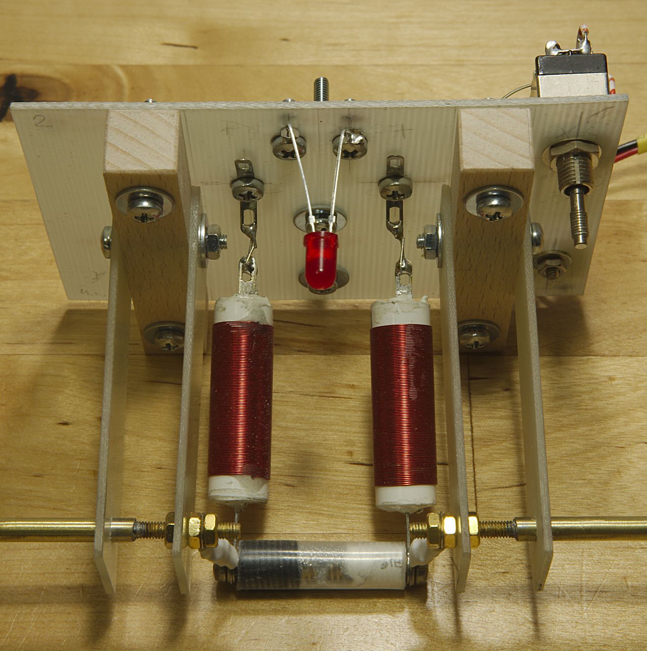 |
Picture 4: Details of the coherer receiver
[1] Herbert, Nick (1987): Quantenrealität: jenseits der neuen Physik. Aus dem Englischen von Traude Wess. Basel, Boston: Birkhäuser. ISBN 3-7643-1871-6
[2] Bose, J.C. (1899): On a Self-Recovering Coherer and the Study of the Cohering Action of Different Metals. Proceedings of the Royal Society: London, vol. LXV, no. 416, pp. 166–172: Publisher Item Identifier S 0018-9219(98)00763-4; Reprint in PROCEEDINGS OF THE IEEE, VOL. 86, NO. 1, JANUARY 1998
[3] Falcona, Eric; Bernard Castaing (2005): Electrical conductivity in granular media and Branly’s coherer. A simple experiment. Laboratoire de Physique, E´cole Normale Supérieure de Lyon, UMR 5672, 46, allée d’Italie, 69 007 Lyon, France: Am. J. Phys., Vol. 73, No. 4, April 2005
[4] http://www.radio-electronics.com/info/radio_history/radiohist/coherer-history.php
[5] Solari, Luigi (1942): Marconi. Im Privatleben und bei der Arbeit. Aus dem Italienischen von Theodor Lücke. Leipzig: Paul List Verlag
Last modification: August 17 - 2015 DF2IR